The Ring Pro is designed for the US market where their doorbells operate at higher AC voltages. In the UK the standard household operates with lower AC voltages (around 8V AC) and so the Ring Pro in the UK comes with a power converter kit. You get a transformer and a solenoid bypass kit (which is effectively a 50W resistor).
My house was installed with a Friedland 752 transformer and and Friedland 214 door chime. I had both a front door and a back door push button wired up.
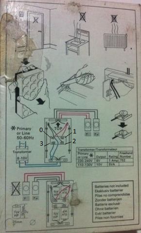
The first thing I had to do was figure out the wiring. I isolated the transformer, took the cover off the door chime and compared the wiring to an old diagram I found on the Internet. Note that inside the door chime there is a label and an arrow pointing "Top". Use this to align the chime correctly (mine was installed upside down with Top pointing downwards!). The diagram isn't very clear, but there are actually 3 wires connected to terminal 0 (one half of the AC transformer source and then one connection out to each of the two buttons).
By disconnecting the wires in turn and using a multimeter I found that the front door bell made the connection between terminal 2 and one of the wires screwed into terminal 0.
| Terminal | Description |
|---|---|
| 0 | Multiple wires: A. Common transformer connection, B. To Front push button, C. To Back push button |
| 1 | Return from Back push button |
| 2 | Return from Front push button |
| 3 | Transformer connection |
Thus the wires screwed into terminals 2 and 3 were disconnected and pushed into the bypass unit. This puts the resistor in series with the Ring Pro, across the AC output.
To house the transformer I purchased a Wylex ESE2 IP40 2-Module Unpopulated DIN Enclosure from Screwfix (it cost less than £5).
I removed the old Friedland transformer and installed the new Ring transformer inside the Wylex enclosure. I wired up the mains connection and the 24V output.

No comments:
Post a Comment